CS 111
Scribe Notes for 11/06/13
Lecture 11: File System Design
By Sangyeop Lee
Some I/O performance and Metrics
There are several metrics that can be used to gauge how efficient your file system is
The below three metrics require our attention, as they play critical roles in gauging the efficiency of our file system.
Utilization measures what percentage of your system is doing useful work. The ideal utilization value would be 100%
Throughput is the measure of how many requests get handled per second. Ideally, throughput should be as fast as possible.
Latency is defined as the delay between a request and response by the file system to that request
I/O Performance Example
Now, let’s assume that we have a hypothetical router device that is flash drive type
, and our goal is to design this router to be nicely balanced in terms of cost and efficiency;
Therefore, this router should demonstrate high utilization, low latency, and high throughput with a relatively affordable CPU.
Figure 1 A hypothetical router
We make a set of assumptions about this hypothetical router
Now that we have given properties to this router, how can we efficiently program our hypothetical router device to grab files from hard disk with
lowest latency, highest throughput, and highest CPU utilization possible?
Method 1: Polling (This is the simplest approach)
In this approach, we further assume that we are grabbing one byte at a time. We send command to the hard disk and constantly check the disk to see whether the disk is ready (Remember that in the bootstrap example, where polling was also used, we handled one sector at a time, not one byte at a time)
Method 2: Batching
This time we can grab a lot more data than just one byte. We choose the batch size of 21*40. However, there is one downside to batching,
the first request takes longer to proceed, and this results in an increased latency.
But one upside is that we are getting rid of overhead of individual byte reading by switching to batching.
Method 3: Batching + interrupt + context switching
Interrupt allows the router to do other work instead of polling for the hard disk being done. The key idea of this approach is to use multitasking,
so that while we are waiting for the data to be ready, we give up CPU control to another process to do another task.
However, due to the overhead of context switching, throughput and CPU utilization go down, although latency decreases compared to method 2.
Method 4: Direct Memory Access
Disk controller can talk to the RAM in the router directly by using signals. Direct access to the RAM significantly improves all three metrics.
However, there is still the overhead of context switching.
Method 5: Direct Memory Access + Polling
This is by far the most efficient approach. In this approach we get rid of multi-threading, since context switching is so slow.
Instead, we rely on purely event-driven approach, where CPU waits controller to say it is ready.
Moreover, assumption 8 states that there are a lot of work to do for this router. Therefore, polling time will be substantially reduced.
If the router does not have a lot of work to do, utilization may shrink.
Here is the overview of the performance of each method
Method | Latency (μs) | Throughput(kB/s) | CPU Utilization |
Polling | 100 | 10 | 5% |
Batching | 1000 | 21 | 10.5% |
Batching + Interrupt + Context Switching | 106 | 18 | 8.9% |
DMA | 61 | 91 | 45% |
DMA + Polling | 56 | 167 | 84% |
Figure 2 Table to compare the overall performance of each method
File System Design
How do we design a file system?
Let’s start with the least efficient file system (RT-11 file system)
RT-11 (Paul Eggert File System)
File System Structure
In 1974, when Professor Paul Eggert was still a 19-year-old college student, he was entrusted with the exacting task of implementing a file system for a 1.5 foot diameter,
1 mega-byte hard disk cartridge. He was using a language called BCPL. After completing this task, Professor Eggert realized that he had basically reinvented RT-11 file system.
RT-11 file system was originally designed by Digital Equipment Corporation.
Below is the structure of the file system
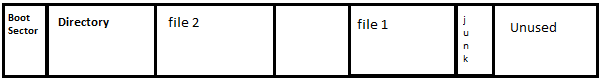
Figure 3 Overview of the RT-11 (Paul Eggert) File System. Junk takes up about half a sector (256 bytes). Junk is allocated whenever a new file is allocated.
By using this approach, professor Eggert stored files in contiguous sectors.
Furthermore, file location was defined by the starting sector of the file.
Note that professor Eggert did not implement superblock for his file system design.
Then, how can the program know where files are in the disk? Obviously, he needed to implement some way to keep track of where the files are.
To address this issue, professor Eggert put a table of files that keeps track of where files are in front of this array (at the beginning of the disk),
and he called that table Directory. his table took up about 8 sectors, and had 32 entries.
Directory is also stored like a file in RT-11 file system array.
Each entry in the directory would look like the following.
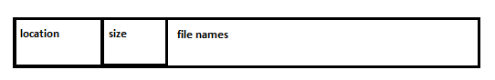
Figure 4 Structure of each directory entry
Now, let’s take a look at some of the advantages and disadvantages of RT-11 file system.
Advantages
RT-11 file system is very a) simple , and it has b) low-index overhead. Since the files are laid out contiguously in a linear array, RT-11 system also boasts
c) fast sequential access and d) fast random access. Moreover, since the data is laid out contiguously and sequentially, this file system is very e) predictable.
Disadvantages
Although RT-11 file system is easy to implement and appear to have appealing features, it has a set of serious problems.
First problem is a) internal fragmentation. This problem arises because a newly allocated file wastes on average half of a sector (256 bytes).
So there will be a huge waste of space.
Second problem is b) external fragmentation. This problem arises since free spaces exist but not contiguously. Therefore, free spaces reside between allocated blocks.
Therefore, even if there are enough free spaces for a large file, the large file cannot be allocated,
since free spaces are dispersed throughout the file system
(One most common solution to external fragmentation is defragmentation, the process of rearranging data, so that unused spaces (fragments) become contiguous).
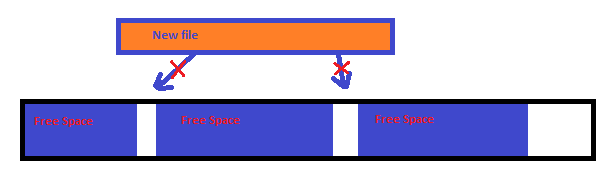
Figure 5 External Fragmentation. A large file cannot be allocated, since free spaces are
Interspaced between allocated data.
The third problem is when c) directory order is not equal to data order.
Since the order of entries in the directory is not necessarily the same as the order of files in the data sectors,
visiting files in directory order might make the disk arm move more than it has to.
The fourth problem is that d) files cannot grow easily because they might run up against next file due to the contiguous nature of the file allocation.
(One solution is to require size estimate on creation)
The last problem is that e) number of files is limited.
Among these problems, the two problems that we wish to solve are 2 ) external fragmentation and 4) files cannot grow easily.
These two problems were solved by the inventors of DOS. Interestingly, the inventors of DOS were not experts at Operating Systems at that time.
They managed to create a more efficient file system than RT-11 with hard work. This new file system is called FAT, or File Allocation Table.
FAT
File System Structure
Just like RT-11 file system, FAT system can be mapped to one long array of sectors.
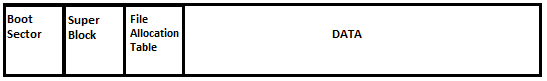
Figure 6 Overall structure of FAT file system
The first sector is reserved for the boot sector.
Super block contains the meta-information about the entire file system, such as the FAT version, size of the file system (How many sectors are in the entire file system),
block size, FAT length, etc. Super block also contains root directory sector, which is the first sector that comprises the root directory.
File allocation table gives all the information about the file system. This table keeps track of all the data blocks that are allocated for a file.
FAT allocates data in fixed-sized units called blocks. One key advantage of FAT file system is that a file can be split into different blocks in different locations on the hard disk.
Since each file can be split into different blocks and occupy interspersed free spaces, external fragmentation is eliminated.
There are many different versions of FAT file system. However, we will examine FAT 16.
File Allocation Table structure for FAT 16
Each entry in the File Allocation Table is 16-bit.
File allocation table is a table of linked-lists of integers.
Each entry is indexed by sector number, and each entry in the FAT also tells you the location of the next entry (the first sector number of the next entry).
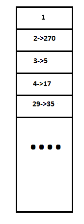
Figure 7 Structure of File Allocation Table
There are special values that FAT table uses to indicate free block or end of file
Therefore, FAT file system allocates new files by going through FAT table to search for entries that have their values set as -1 (free blocks).
FAT file system also has a unique directory structure that distinguishes it from that of RT-11 file system.
While directory is a special region in RT-11 file system, directory is a file that maps file names to other files in FAT file system.
One key feature of FAT directories is that it can have subdirectories.
There are at least two types of files: directory (D) and file (F). Directory is an array of directory entries.
A directory is laid out like the following in FAT file system
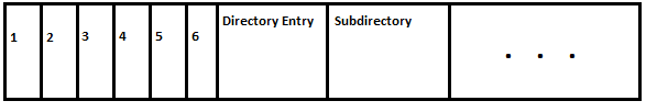
Figure 8 Directory layout for FAT 16. A directory consists of several directory entries.
Since directory has a field that tells us the sector number of the first sector of the file, we can refer to FAT to find the blocks that make up the rest of the file.
However, if we were to read data from a file, the disk head may need to move from FAT to a data block and then back to FAT.
Such action is repeated until end of file is reached on FAT. Repeated trips between FAT and data blocks may slow down the performance.
Therefore, we may be able to cache the FAT into RAM, so that the disk only has to move from one block to another block without visiting FAT.
However, if FAT gets too large, we cannot cache it in RAM.
Advantages of FAT File System
Disadvantage of FAT File System
One key disadvantage is that moving files between directories can corrupt the file system, or lead to a disaster.
For the purpose of explaining this disadvantage, let’s assume that writing operation is atomic.
Suppose that we want to rename a file.
In RT-11 file system, renaming a file is very easy, since all you have to do is to go into the table at the start of the file system and update the name of the file that is stored in that table. In FAT file system, if we want to rename a file in the same directory, it is not that difficult.
However, if we are renaming a file in one directory and moving it to another directory, the problem emerges.
Consider the following operation
-mv d/f e/g
Let’s say that this operation was performed, and now there are two file names for one file.
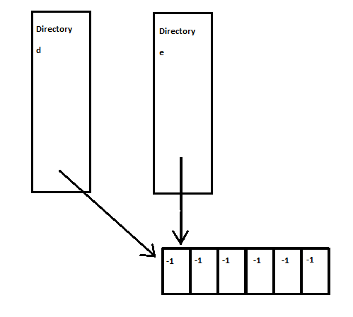
Figure 9 If operations like mv d/f e/g is performed, each directory will point to the same file.
The problem arises when two different directories are pointing to the same file. After reboot, both file names for the file exist in each respective directory entry.
Suppose we remove the file associated with directory d. Then, all the blocks that make up the file are set to -1 to free the blocks for later use by other files.
However, in this case, the blocks are still in use by directory e. It is a serious error if the block is free and in use at the same time.
Designers of FAT were aware of this issue, but they did not implement the method of handling this issue; they simply did not allow this operation for reliability issue.
But how do we design a file system that can handle this operation without worrying about corrupting the file system?
The solution is adding a level of indirection, and this approach was adopted by UNIX File System, which came out around 1975.
UNIX File System
File System Structure
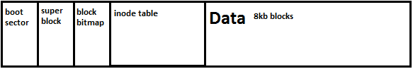
Figure 10 Overall structure of UNIX file system
Boot sector and superblock still exist, just as in FAT file system.
A new set of fields have been added to the structure: a) block bitmap and b) inode table.
For the purpose of this lecture, we assume that each data block is 8kB, or Bytes. Then, if each sector has 512 bytes, each block will span 8kb/512 bytes = 16 sectors.
We also have to note that inode table does not contain file names ; file names are stored in the directory entries instead.
Block bitmap
Block bitmap is an array of bits that tells which block is free. 1 bit is per block. Bitmap size is determined by the number of blocks on the disk.
This field keeps track of free blocks on the disk. If bit is 0, that block is not free. If bit is 1, that block is free for allocating a new file.
The blocks that contain boot sector, block bitmap, and the inode table are always set as 0, meaning that they are always not free.
Inode Table
Each inode in inode table contains basic information about a file or a directory (size, permission, type, the number of directory entries that are currently pointing to it).
Inode table is indexed by inode numbers. Each inode corresponds to one file or one directory. Inode does not contain information about file’s name and directory location.
Directory entries point to inodes by inode numbers. We assume that each entry in inode is 32-bit fixed size for the purpose of this lecture.
Each Inode is laid out like the following:
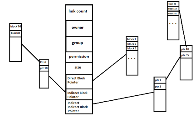
Figure 11 each inode is organized in the above way.
With the use of indirect block pointers, about ((2048*8192)/(2048*2048*8192))*100 = 0.0488 % of the disk is wasted, which is far less than 1%, showing a high utilization.
UNIX file system partitions files into several block pieces.
For small files, we use direct block pointers. However, for large files, we use indirect block pointers or indirect-indirect block pointers.
Directory Entry in the original UNIX file system was 16 bit.
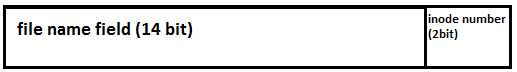
Figure 12 Directory entry structure for UNIX file system.
The first fourteen bits were allocated for filename, and the last two bits were allocated for inode number.
One important point that we must observe is that a directory cannot point to itself, since that would result in cycle (This problem also existed in FAT system).
Therefore, whenever a directory file name is to be renamed, file system code must make sure that the resulting directory hierarchy has no cycle.
For this reason, renaming a directory requires a cycle check, which is an expensive operation.
In the original UNIX file system, renaming a file and moving it to another directory was not allowed either (recall mv d/f e/g).
Instead, UNIX file system used two system calls that would enable that operation.
Link() and unlink()
Performing mv d/f e/g using link and unlink system calls
Unlink does not free the file blocks immediately. The link count field in inode shows the number of directories currently pointing to that inode. File can only be freed if link count is 0,
and the file is not open. Using this approach is much more stable, since, if you now remove the file that is renamed, you don’t trash your file system anymore.
However, between link and unlink operations, there could be crash, such as power failure. such power failure can mess up the link count.
This issue will be addressed in the next lecture. If you lseek() a file, you can find the block right away in inode table.
Therefore, lseek() is much faster in the UNIX file system than it is in FAT file system.
If you ask UNIX file system what the name of a file is, it can have three names if link count is 3. However, if link count is 0, that means the file is nameless.
Link count 0 can represent a situation where all the names of a file have been removed, but at least one process has the file open.
The downside of having a file that has link count 0 is that you can create a very large nameless file that takes up a lot of space.
Indeed, in UNIX file system, we can create files with holes between data block pointers. Holes are unallocated spaces. We can allocate data by writing to holes.
For example, there can be an inode with most block entries set to 0, and one entry pointing to block 57.
Below is one such example
$echo x | dd seek = 1000000000 bs = 1000000 > file
This command performs an lseek of billion times million and write x followed by a newline at the end of billion times million offset.
Therefore, a new file is created that has a lot of holes and a large size.
However, if we perform ls command with –ls option to print the allocated size of the file in blocks.
$ls -ls file
: 16 -rw-r—r ….
ls –ls command returns 16, since we did not actually allocate that much data.
Now, let’s summarize important advantages and disadvantages of UNIX file system.
Advantages
Disadvantages
Since the file system must iterate through the entire bitmap field to see which bits are free, searching a free block for allocation is quite expensive.