In the previous lecture, we began developing our paranoid wc
(word count) program that requires no operating system. To review our
design, our program, written in standard C, would read its input from
halfway through the hard disk until it encounters a null byte,
\0, then counts the number of words in this file. A word is
defined with the regular expression [A-Za-z]+. The word count
is then printed on the screen. The program is executed by pushing the power
switch.
In this lecture, we will complete our wc program. Last time,
we figured out how to load our program, read the input from disk, and count
the characters. We now proceed to printing the result on the screen. To do
so, we must introduce the concept of memory-mapped input/output.
In the last lecture, we accessed a device, the hard drive, using the CPU's
input/output instructions. There is another way to access a device, called
memory-mapped input/output, where the device state is exposed at a certain
memory location. The CPU can read and write to it just like any other memory
location, but unlike other memory locations, the device we want to access is
also reading or writing from that memory location. On IBM PC-compatible x86
machines, the screen device is exposed as a memory-mapped input/output
device. The screen on IBM PC-compatible machines can be configured in many
different modes, but we are only interested in one mode. In the screen mode
we use for our wc program, the screen can only display ASCII
text and 16 colors, which is all we need. In this mode, the screen device is
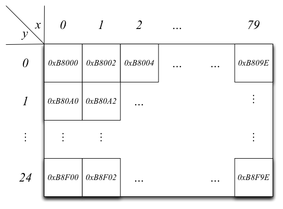
mapped to memory location 0xB8000. The resolution of the screen
is 80 characters horizontally by 25 characters vertically. The screen
characters are laid out in row-major order, such that a row of characters is
contiguous in memory. Each character is represented by 2 bytes: the first
byte contains color and blink attributes, and the second byte is the ASCII
value of the character to be shown. Thus, the screen buffer is 80 × 25
× 2 = 4000 bytes long, and is located from 0xB8000 to
0xB8FA0 in memory. The following diagram shows the screen
buffer layout:

The following diagram shows the structure of each 2 bytes that represents a character:

Now that we know how the screen works, we will write the display output
routine for the wc program:
void
display (int word_count)
{
  char *screen = (char *)0xB8000;
  char *p = screen + 2050;
  int digit;
  do
    {
      digit = word_count % 10;
      *p = digit + '0';
      --p;
      *p = 7;
      --p;
      word_count /= 10;
    }
  while (word_count);
}
Our first version of the program used the CPU's input/output instructions to read from the hard disk. This approach is simple but slow, because often you want to read more than one byte at a time out of disk. Another approach is called direct memory access or DMA, wherein the device can read or write directly to main memory. The CPU tells the device
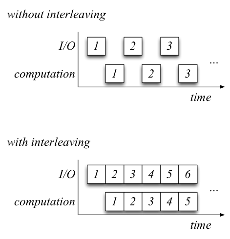
and the device goes off to execute the direct memory access. DMA is much faster than using the input/output instructions to read byte by byte, because this frees the CPU from having to do input and output. A program generally spends its time doing one of two things, input/output or computation. Most of the time is spent in input/output because modern CPUs are several orders of magnitude faster than input/output devices. Therefore it makes sense to optimize the way a program does input/output. With DMA, since the device and not the CPU performs input/output, input/output can be interleaved with computation, making the program faster. The following diagram compares a program without and with interleaving (the numbers represent chunks of data):

Say we decided to use interleaving to speed up our wc
program; we thus modify our program's read_sector function to
do so. Now we have two read_sector functions: one in the
wc program itself and one in the bootloader. This is now a
software engineering problem, as we now have two functions that perform the
same thing and that we have to maintain and update. One way we could solve
this problem is that we could discipline our programmers. We could have
just have one copy of read_sector that we place in a fixed
location in the BIOS. There are a few problems with this: The BIOS is
limited in size, so this approach doesn't scale; you will want to add more
and more functions to the BIOS and you will eventually run out of space.
It is hard to update the BIOS; as it is not software anymore, it is
firmware.
Our wc program has many downsides: it is
There are many more problems like the ones listed above. Thus, this approach of writing applications to run on the bare machine adds complexity and doesn't scale. There are two techniques to deal with such problems:
There are some metrics to help us define nice boundaries:
Optimizing for one metric often causes other metrics to suffer: this is called the waterbed effect. (Pushing down one end of a waterbed will cause the other end to rise.)
So how shall we support modularity? There are several ways:
read_sector (a, b);pushl a
pushl b
call read_sector
addl $8, %esp
read_sector itself compiles down topushl a
movl 8(%esp), %eax
movl 4(%esp), %eax
...
ret
switch (*ip++)
  {
  case MOV:
    ...
  case ADD:
    ...
  case RET:
    ...
  }
int x where x is a
number. This instruction, when execute, saves 6 words of machine state:
SS (the stack segment), ESP (the stack pointer), EFLAGS (the flags
register), CS (the code segment), EIP (the instruction pointer), and the
error code, and jumps to the interrupt service vector which
points to operating system code. When the interrupt service routine
executes, the CPU is now in privileged mode. This code executes the
operating system routine; when it is finished, it executes the return from
interrupt instruction, rti. This approach allows the
operating system to be well-isolated from the application, allowing better
modularity and abstraction. The downside of this approach is that it is much
slower than a regular function call.sysenter and
sysexit instructions. The sysenter instruction
sets the CS, EIP, SS, and ESP registers from special "shadow" registers and
then jumps to the sysenter handler in the operating system. The
sysexit instruction restores the registers and then jumps
back to the application. These instructions are faster because they avoid
the overhead of handling interrupts.sysenter/sysexit method of system calls depending
on what the CPU supports. It abstracts away these machine details with a
special library that is linked in with every application. If you execute the
following command in Linux,$ ldd /bin/shldd will return something that looks likelinux-vdso.so.1 => (0x00007fff5c99f000)
libtinfo.so.5 => /lib64/libtinfo.so.5 (0x0000003ca0200000)
libdl.so.2 => /lib64/libdl.so.2 (0x0000003c92200000)
libc.so.6 => /lib64/libc.so.6 (0x0000003c91600000)
/lib64/ld-linux-x86-64.so.2 (0x0000003c91200000
linux-vdso.so.1 is the system library that abstracts away
the system call mechanism.