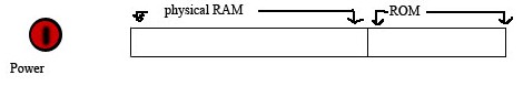
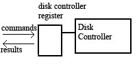
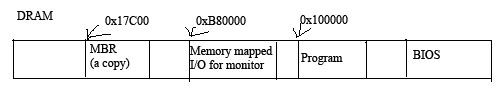
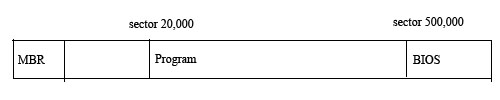
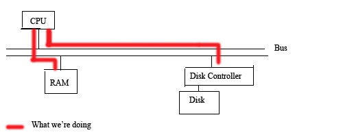
Lecture #2: How Not to Write an Operating System!

Q & A (Requirement Illicitation)

Issues

  1. bootstrapping
  2. disk input
  3. screen output

Bootstrapping

Memory Setup
Physical memory is divided into two pieces: RAM (random access memory) and ROM (read-only memory). ROM is nonvolatile storage, which means it doesn't disappear when power is turned off. Usually it contains whatever the hardware manufacturer has installed by default. There is also "boot Programming ROM" (boot PROM) which contains the BIOS.

The BIOS works as follows:
  1. It tests the system (e.g. tests the RAM and hardware).
  2. It looks for devices
  3. It looks for a readable device containing a Master Boot Record (MBR):

    MBR Layout

    The MBR standard form. It contains 3 sections, a machine instruction section, a partition table, and a signature. The machine instruction for x86 is 446 bytes long. The partition table is 64 bytes long and has 4 entries. Each entry has 16 bytes. A partition table can partition the MBR for linux, windows, apache. Each entry contains the status and type of the partion. (am I bootable? what type?). Also has the start of where on disk the partition starts and the size of the information. The MBR has a signature, 0x55 0xAA, at the end to denote that it is a MBR.
  4. It reads MBR into disk RAM and jumps to it. (An interesting note: if the beginning of the machine instruction is the x86 HALT instruction, the computer will never do anything. Try it on your friends today!)

Disk Properties

Disk Controller
The commands issued for CPU to read the disk:
  1. Wait for the disk to be ready (CPU reads location 0x1F7).
  2. Store # of sectors you want to read into location 0x1F2.
  3. Store sector offset into locations 0x1F3 - 0x1F6. The sector offset is disk location, given by a 32-bit quantity. This allows for referencing up to 2^32 * 2^9 = 2^41 bytes.
  4. Store READ command into location 0x1F7.
  5. Wait for disk to be ready.
  6. Get results as a sector into CPU.
  7. Store results into RAM.

Our MBR Program

The MBR is 446 bytes in size and includes the location of our program.

MBR Layout
The BIOS is always copied to location 0x17C00, while the MBR program location is arbitrary.

Disk Layout:
Disk Layout
We assume the program is at sector 20,000 and that the program is 20 sectors long.

MBR Program Code
int main(void){
	for (int i = 0; i < 20; i++){
		read_ide_sector(20000 + i, 0x100000 + i * 512);
		goto 0x10000;	// NOTE: Not proper C language!
	}
}

void read_ide_sector(int s, int a){
	while((inb(0x1F7) & 0xc0) != 0x40) // inb = inbyte
		continue;

	outb(0x1F2,1); // Outbyte # of sectors
	outb(0x1F3, s & 0xff);
	outb(0x1F4, (s >> 8) & 0xff);
	outb(0x1F5, (s >> 16) & 0xff);
	outb(0x1F6, (s >> 24) & 0xff);
	outb(0x1F7, 0x20); // Read sector

	while((inb(0x1F7) & 0xc0) != 0x40)
		continue;

	insl(0x1F0,a,128); // Where, data, copy # of 4-bytes units
}
Main Program Code
int main(void){
	char buffer[512];
	int nwords = 0;
	bool in_word = false;

	for (int s = 500000;; s++){
		read_ide_sector(s, (int)buf); // Typecasting buf

		for (int j=0; j < 512; j++){
			if(!buf[j]){
				write_out[nwords];
				return;
			}

		bool this_alpha = isalpha((unsigned char) buf[j]) != 0;
		nwords += this_alpha & ~in_word; // ~ means invert bits; has the same effect as !, but is generally faster, increment word count
		in_word = this_alpha; // Now in a word
		}
	}
}

Screen Output

Monitor Layout

The monitor can be thought of as a 25 * 80 * 2 = 4000 byte array, with 2 bytes representation for each "pixel" on the 80 x 25 screen. The high byte contains color info, while the low byte contains the ASCII character to print out.

Screen Output Code
write_out(int nwords){
	unsigned char *screen = 0xB8000 + 20; // 10 chars into screen
	do{
		screen[0] = (nwords%10)+'0';
		screen[1] = 7; // Gray on black
		screen -=2;
		nwords /= 10;
	}while(nwords);
}

Performance Improvements

We could improve on how we read from the disk.
Monitor Layout
Ideally don't use write long command. Instead, we read and write at the same time. The technique for this is called direct memory access (DMA).

Normally, this is the timeline for what happens in our program.
Timeline
Normal operation: Send command, wait, then compute

We can optimize so that it works as follows:

Alternate Timeline
Optimized operation: Send command while waiting and compute while waiting