Borys Boyko
Garret Buell
Matt Hanson
Complexity in Computer Science
UNIVersal Automatic Computer I (UNIVAC I)
The UNIVAC I ( link1, link2 ) was the first commercially successful computer in the United States. It designed on paper as there were no computers to simulate its hardware. Because they were unable to verify the correctness of their design electronically, the creators of UNIVAC I implemented extensive error correction circuitry. This conservatism was one of the reasons that allowed the UNIVAC I to succeed in the marketplace. The engineers at Remington Rand used the UNIVAC I to optimize the UNIVAC II1. The error correction circuitry was stripped out of later models as it was deemed unnecessary. This type of feedback loop is modeled by the following first-order differential equation:
d(Technology)/dt  =  k * T
Technology = Ae^(kt)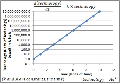
Scaling, Emergent Properties, and Propagation of Effects
DNS Protocol
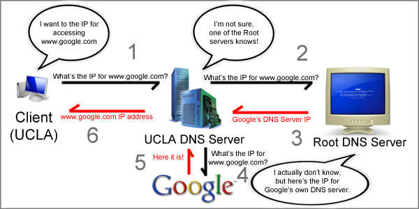
When a user accesses the Internet, he or she may visit websites such as www.google.com. However, the user’s computer does not know where to find www.google.com. In order to actually connect with a website, the user’s computer needs some way to translate the domain name into an actual IP address. DNS protocol ( link1, link2 ) is the process by which this translation takes place.
When a user looks up a domain name, the request is sent to a DNS server. There are many DNS servers around the world: UCLA keeps its own DNS server locked in the fourth floor of Boelter Hall. A user who is connected to the UCLA network will most likely query this server when trying to lookup a domain name.
The DNS server at UCLA cannot immediately provide the user with an answer (unless the particular domain name requested has been cached.) Rather, UCLA’s DNS server makes its own request to a root DNS server. There are only 13 root DNS servers in the world, and their IP addresses are well known so that other DNS servers can easily send them requests. The root servers may not be able to satisfy the user’s entire request, but they will supply the local DNS server with new information that will lead to the correct IP address. The figure below illustrates this interaction.
Kaminsky Design Flaw
The DNS is build on top of a UDP protocol, which is made up of packets containing a sender’s IP, a recipient’s IP, the length of the packet, a checksum, and a payload of data ( link1, link2 ):

Although root servers are kept very secure, malicious hackers can exploit this simple protocol by injecting false packets (for example, packets containing false IP addresses for the client to access) into the internet (potentially using a bogus sender’s IP address.)
During the summer of 2008, Dan Kaminsky exposed several serious vulnerabilities in DNS ( link1 ). There are several defense mechanisms available to prevent such attacks:
- DNS servers can check packets for correct sending IP address of the root DNS server
- Attackers can easily break this defense by either common sense or brute force. DNS servers will tend to communicate with the nearest root DNS server. If this fails, it is not too much trouble to inject 13 malicious packets. However, it is suspicious, so hackers tend to guess correctly on the first try.
- DNS servers can check packets for correct request (checksum) numbers, which are 16 bit numbers.
- This too can be bypassed with a little cleverness on the part of the attacker. He or she can check the request numbers of the most recent packets, and narrow down possible request numbers to a small range of values that would probably follow the just-used request number.
- DNS servers can randomly generate request numbers
- Although this decreases the likelihood of a successful attack, it does not prevent it. Attackers can increase their gains by attempting to hijack authority records (add link, couldn't find one). Once they have access to authority records, attackers have control of an entire subtree of namespaces. This type of attack is called poisoning a nameserver cache, as an attacker who has control over a nameserver’s authority record can specify how long the bogus IP addresses should be cached. If a DNS server is compromised, flushing the cache will fix the problem. However, it is necessary to know that the server is getting attacked to be able to respond quickly.

We can attribute the DNS design flaw to:
- Propagation of effects
- When a nameserver is compromised, all users who rely on that nameserver are subject to the will of the attacker
- Lack of scalability
- DNS was developed in 1982, when few hosts existed. Only corporations and universities had access to the Internet, so this kind of attack was not a very real concern. However, the explosion of the Internet has created many new security concerns.
- Emergent properties
- The development of DNS led to the development of caching and queries. Also, while the simplicity of the UDP protocol is a desirable feature, it has the unintended consequence of opening the door for packet injection attacks.
Poorly Designed Operating System from Scratch
We have been hired to write an application that will output the word count of an ASCII text file. Our employer is a paranoid English teacher who dreams of winning an award from the MLA. She is working on a new, top-secret essay which she believes will be the winning paper. In order to keep her essay a secret from spies at Microsoft and Ubuntu, she wants us to build her an operating system from scratch. We don’t have much experience in building our own operating systems, but we’ll do our best. Additionally, some of us have not taken CS 130 yet and our software engineering skills leave something to be desired. The resulting operating system will be hacky, minimal and fast, but it will get the job done.
Here’s our specification:
- Our OS and application must be completely made up of our own code
- Our OS must be as fast as possible
- Our application must be very easy to run: the word count should appear on the screen as soon as the computer boots after being plugged in.
- We are working on an IBM 32-bit x86 system with 1 GB of RAM (Random Access Memory) and a 100 GB SATA disk drive. We have a functioning BIOS (Basic Input/Output System) ( link1, link2, link3 ) and an alphanumeric display.
This seems simple enough. But there are still some issues that we need to resolve.
Bootstrapping
We need to bootstrap the OS so that it will run as soon as the computer is plugged into a power source. When the computer is turned on, the program counter is set to the address at the beginning of the BIOS. A standard BIOS will perform a self-test immediately upon startup. This test consists of checking the integrity of the RAM (by writing and reading to it) and the BIOS ROM (read only memory) itself, as well as querying for devices. The following is the structure of memory in a computer:

A bootable device is defined to be a device whose first 512 bytes follow the format of a Master Boot Record (MBR). The MBR ( link1, link2, link3, link4 ) consists of 446 bytes of x86 code, a 64 byte partition table, and a 2 bit signature that validates the existence of the MBR.

The structure of a partition table entry is:

The x86 code within the MBR is a small program which will read the partition table, looking for a bootable partition. Once such a partition is found, the first sector (512 bytes) from that partition is loaded into RAM. This process is repeated until the bootable part of the partition has been entirely loaded into physical memory.
Chained Loading
The BIOS is responsible for loading the MBR, which may be required to load what is called a Volume Boot Record (VBR). A VBR ( link1, link2 ) is typically OS-specific, meaning that it knows the important disk locations such as where to begin loading another VBR from (if necessary), or where the operating system is located. Below is the structure of a drive with four partitions, one of which has a volume boot record.

This multi-level booting process is known as chained loading. After everything has been loaded, memory may look something like this (for our purposes, we will set the program's starting sector at 0×10000 in the memory):

Note: The size of a VBR is usually indicated by a size field at the beginning of the VBR. The end of a file in memory is usually indicated by a null byte at the end of the file.
Disk Drive Controller
| Disk Location | Function |
|---|---|
| 0×1F7 | Wait for ready (first two bits being 01 signals ready) |
| 0×1F2 | Number of sectors |
| 0×1F3-0×1F6 | Sector offset |
| 0×1F0 | Data register |
Now it's time to write the code for the program. The following will occur:
- Wait for the disk drive to be ready (by reading 0×1F7)
- Set the number of sectors we wish to access into 0×1F2
- Set the sector offset in 0×1F3-0×1F6
- Set the read command into 0×1F7
- Wait for the disk drive to be ready
- Get results into CPU and store into RAM
We will assume that the program is 19 sectors long. The VBR instructs reading the program beginning at the 1st sector (0 sector is reserved for the VBR):
// here, it is assumed that 19 is the size of the program, in sectors;
// begins at sector 1 because sector 0 is the VBR
for(i = 1; i < 20; i++)
	read_ide_sector(i, (char *)(0x100000 + (i - 1)*512);
// assume that the program's address is at 0x100000; this is not proper C code
goto 0x100000;
Next, we will write a function that will wait for the drive's 0×1F7 location to signify that it is ready.
void wait_for_ready(void) {
	while (inb(0x1F7) & 0xC0) != 0x40)		// busy wait
		continue;
}
The following function allows reading from an IDE sector.
void read_ide_sector(int s, int a) {			// program for reading an IDE sector
	wait_for_ready();
	outb(0x1F2, 1);					// stores 1 into the "# of sectors" register
	outb(0x1F3, s & 0xFF);				// sets the sector offset register
	outb(0x1F4, (s >> 8) & 0xFF);
	outb(0x1F5, (s >> 16) & 0xFF);
	outb(0x1F6, (s >> 24) & 0xFF);
	outb(0x1F7, 0x20);				// read sectors (sets ready register)
	wait_for_ready();
	insl(0x1F0, a, 128);				// insert long
							// (128 * 4 bytes per word = 512 bytes total,
							// which is the sector's size)
}
Now, the main program.
void main(void) {
	unsigned long int nwords = 0;
	bool in_word = false;
	long int s = 2000000;				// chosen initial sector
	for (;; s++) {
		char buf[512];				// buffer for reading
		read_ide_sector(s, (int) buf);		// read IDE sector to the buffer
		for (int j = 0; j < 512; j++) {
			if (!buf[j]) {			// check if a word is being processed
				nwords += in_word;
				write_out(nwords);	// display word count
				return;
			}
			bool this_alpha = isalpha((unsigned char) buf[j]);
							// true if the character is alpha
			nwords += this_alpha & ~inword;
							// increments the number of words before each word
			in_word = this_alpha;
							// updates whether the "marker" is in a word
		}
	}
}
Finally, we need a function for displaying the results on the screen.
void write_out(int n) {
  char* screen = 0xB8000 + 50;
  // starting position for writing to display; 16 bits per character, the 50 is to be safe
	do {
		screen[0] = n % 10 + '0';
		// sets the array to the appropriate ascii character code for the digit
		screen[1] = 7;
		// black background, gray text
		screen -= 2;
		// writes from back to front (not noticeable to user), moves back 2 bytes
		n /= 10;
	} while(n);				// stops when n = 0
}
The program can be improved in several ways. For example, it can be reprogrammed to read from more than one sector at a time and to perform computations and send instructions while waiting for the disk drive to be ready. This increases activity and prevents unnecessary idling of the system's components.
Some problems will still exist. These include the inability to read from multiple devices, the complexity of the program (a user with little knowledge will not be able to alter the way that the computer works), the lack of parallelism, and the lack of error prevention should something go wrong (ex: overflow).