A paranoid English professor working on a paper needs to count the words in a file. The professor is afraid of prying eyes, so they ask us to write the program with the following constraints:
As software engineers, we ask a few questions about the project:
What are the machine specs?
What is the file format?
[A-Za-z]+.NULL bytes.Are there any possible future extensions?
What is the output format?
With this information we begin to look at how such a program can be written.
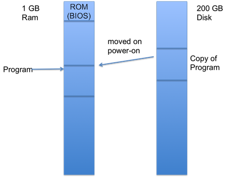
First we need to figure out how to start our program. This involves loading our program into memory and then setting the instruction pointer to the start of our program.
We run into the following problem: how do we load our program into memory? We can’t store our program in RAM, since when the power is turned on the RAM will be reset. The only place where we can store the program is in the machine’s PROM (programmable read-only memory) or on disk.
In the old days, users would manually flip switches on a computer in order to set its instruction pointer. This is an unwieldy process, however, so today’s machines are designed to start with the instruction pointer pointing into the boot PROM. What if we reprogrammed this ROM to run our program? We avoid this option for a couple of reasons:
Thus instead we will use the machine’s own bootstrapping process to start our program.
The PROM contains a tiny program called the BIOS (basic input/output system), which is run when the machine starts. The BIOS performs the following tasks: It tests the system, looks for connected devices, attempts to find a device with a MBR (master boot record) and boots it.
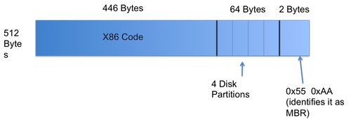
A Master Boot Record is a 512 byte record (one sector) which sits at the beginning of a disk. It signifies that the disk is bootable. A master boot record is identifiable by its last two bytes: 0x55 and 0xAA. The remaining segments of the MBR are broken into 446 bytes of code, which run the next part of the bootstrapping process, and 64 bytes which describe the disk’s partitions.
The BIOS reads the MBR into RAM at location 0x7c00, and the instruction pointer is set to 0x7c00. Now the 446 bytes of code from the MBR are run. We could potentially try and fit our word count program into this space, but it would cause the same problems as trying to program the PROM to run our program:
Thus we continue the bootstrapping process. The program in the MBR contains a small program which mimics the BIOS in many ways. It looks through the partition table for a bootable disk partition. When a bootable partition is found, the first sector of the partition, called the VBR (Volume Boot Record), is loaded into RAM. The reason we make the distinction between MBR and VBR is because we want our MBR to be OS agnostic. In other words, each operating system can use custom loading code defined in its particular VBR, and all the MBR must do is load the VBR. Finally, the VBR can read our word count program into memory.
So far we have been doing plenty of reads from the disk, but how does this actually happen? A disk is physically composed of several magnetic platters which spin at a high speed (typically 7200 RPM [120 Hz]). A read head hovers just above the platters; it does not touch the platter since that would corrupt the data. A “track” is a circle of data on a platter. Each disk sector (512 bytes) is an arc of a track. It takes roughly 4 ms to read a track and 8 ms for the read head to seek to a track. Since seeking takes a long time we should try and fit both our program and our data into a single track, if possible.
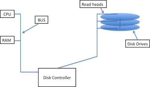
The disk, the CPU, and the memory all reside on a hardware bus so they can communicate with each other. The disk has a very simple machine called a disk controller which allows it to communicate on the bus and perform reads and seeks.
The way we will read from disk in this example is through what is called “programmed I/O”. Programmed I/O is a process in which the CPU orchestrates disk reading and data flows through the CPU into memory.
The CPU performs the following actions:
0x1f7 which contains status codes.0x1f20x1f3 to 0x1f6.0x1f70x1f7Here is some somewhat real code which reads a sector from disk:
void wait_for_ready(void) {
    // inb (short for inbyte) is an x86 instruction (not a function call) that reads one byte
    while((inb(0x1f7) & 0xc0) != 0x40)
            continue;
}

// s is the sector number, a is the memory address where we want to write
void read_sector(int s, char *a) {
    wait_for_ready();
    // outb is also a machine instruction
    outb(0x1f2, 1); // set the number of sectors to read to 1
    outb(0x1f3, s&0xff);
    outb(0x1f4, (s>>8)&0xff);
    outb(0x1f5, (s>>16)&0xff);
    outb(0x1f6, (s>>24)&0xff);
    outb(0x1f7, 0x20);
    wait_for_ready();
    insl(0x1f0, a, 128); // copies 128 4-byte words into location a
}
Using this code, the VBR could load our actual word count program into memory.
Here is an implementation of our word count program:
int main(void) {
    int words = 0;
    bool inword = false;
    int s = 0x100000;
    for (;;s++) {
        buf[512];
        read_sector(s, buf);
        for (int j=0; j<512; j++) {
            if(buf[j] == '\0'){
                words += inword;
                write_out(words); // writes the word count to the screen.
                return;
            }
            bool thisalpha = isalpha((unsigned char)buf[j]);
            words += inword & ~thisalpha;
            inword = thisalpha;
        }
    }
}
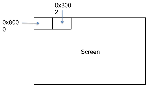
Let us assume that our screen is memory-mapped in the following way. It is addressable as 0xb8000 in the top left corner. The screen is split into 80x25 blocks. Each block is a 16 bit quantity; the low byte is the character to display and the high byte is the color.
void write_out(int n) {
    char *screen = 0xb8000 + (25*80*2/2); // address of the screen's approximate center
    do {
        *--screen = (n%10)+'0';
        *--screen = 7; // code for grey on black
    } while ((n /= 10) != 0);
}
We wrote our own read_sector function, but the MBR and VBR both also need a copy. Why have three? Couldn’t they share a common one? This single copy was originally in the BIOS, hence the name basic input/output system. This is not used anymore since we prefer to use faster methods than programmed I/O (such as DMA, Direct Memory Access).