Abstraction and Bootstrapping
Table of Contents
1 Philosophy cont.
Continuing from the previous class' discussion on the philosophy of systems and design.
1.1 Complexity
Complexity in our digital systems continues to grow. As noted in the book digital systems can grow without bound in contrast to analog systems which have an upper bound imposed by noise introduced by each component.
We will examine a few examples of exponential growth in digital systems and then attempt to explain that growth.
1.1.1 Moore's Law
Moore's Law predicts that the number of transistors on mass produced chips will double approximately every year (class), 18 months 1, or 2 years 2 depending on the source. That is, Moore's law is measured in bits per chip. This exponential growth conjecture was observably true from the 70s when there were merely thousands of transistors until very recently (~2015) with billions of transistors per chip.
Notably, Moore's characterization of the chip production was focused on mass production chips and not exotic chip production methods. Also notable is that the focus is a physical characteristic and not performance, though the two are considered to be closely correlated.
From Wikipedia2:

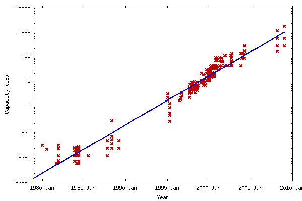
1.1.2 Kryder's Law
Similar to Moore's Law is the less well-known Kryder's law which predicts that secondary storage capacity (eg, disk drives) will also follow an exponential growth curve. Also similar to Moore's law, Kryder's law is defined in terms of bytes on a disk and not the seek time (reads "drive performance").
From David Rosenthal (Stanford University Libraries) 3:
1.1.3 Why exponential growth?
Both in class and in the book the exponential growth is justified as a consequence of a feedback mechanism where the previous generation of processors/disks/technology enable the construction of more complex processors/disks/technology.
For example consider the UNIVAC 1 and UNIVAC 2.
The UNIVAC 1 was the first commercial computer produced in the US 4. It was constructed carefully and many design decisions were made in favor of stability and robust operation (building computers was a new undertaking!).
Once the UNIVAC 1 demonstrated its capacity to solve complex problems quickly and reliably the work of designing the UNIVAC 2 was done partially using the UNIVAC 1 adding an element of speed and certainty to its construction.
This type of feedback is loosely characterized by the following equation:
d(tech)/dt = C * tech
From which we get the value of "tech" as an exponential function of time
t:
tech = e^Ct
Intuitively the growth of tech as a function of time depends on itself.
2 How to avoid using an OS
Why might you want to avoid a full blown operating system to make use of your hardware?
- complexity: operating systems come with an enormous amount of extra complexity which may not be directly related to the problem at hand.
- performance: all that complexity can result in extra overhead even if features are behind flags
- reliability: complexity breads bugs and often hurts reliability
- security: less software/code means less loopholes and sources of compromise with respect to security
The last two can be seen as particularly important extensions of simplicity.
2.1 Example
To explore the idea of using a computer without an operating system we consider an example program that counts the words in a file on the disk.
We make the following assumptions about the construction of the word count program:
- We have a fairly modern machine (~5 years) that with a clean disk that is ready to use
- Someone can get our program and the file onto the disk, the IT dept. etc
- The file will be ascii text, that is each byte corresponds to a character
- The interface is simple, turn the computer on and it dumps the word count to the screen
Given the above, we can begin to build a program, but how? Even if we can get the program onto disk how do we get it to run? We need to tell the CPU to run a program to load our program, but then where does that first program come from? This circular problem is known as the "bootstrapping" problem.
Luckily there are a series of conventions either universal or documented for a given computer that allow us to accomplish the loading and execution of our program.
2.2 Programmable Read-Only Memory (PROM, EEPROM)
The first convention that we can exploit is a bit of non-volatile, read only memory (ROM) that is consulted when the computer is powered on. Of note, improvements adding programability were included to make this more flexible and the name changed accordingly to PROM or EEPROM (for Electronic Erasable PROM).
This bit of memory is reached by requesting a particular address in ram (eg, 220 - 16) but on boot RAM is all null bytes. In fact, the motherboard steps in to forward requests for that memory along to the PROM. This portion of memory is known as the "ROM region".
0                                        4gb
------------------------------------------
  [x]
------------------------------------------
   ^--- ROM region
The story could end here with our program in the PROM but we'd need to get our program into PROM for it to work (maybe by asking the manufacturer) but even then it's not much memory to fit our program in. Moreover, if you do choose to alter the PROM and fail your computer is effectively useless.
We need something else … another convention!
2.3 Master Boot Record (MBR)
Instead of placing our whole program in the PROM we'll use and existing PROM program to load ours from disk. Lucky for us most computers come with a program installed for just this purpose in the PROM called the BIOS (Basic Input/Output System) that will do a few things, again, based on convention.
In particular the BIOS will do some quick diagnostics on the devices attached
to the bus and then look for the first device with a Master Boot Record in
the first 512 bytes of the disk. It identifies these devices by looking for
0x55 0xAA in the last two bytes of the first 512 (here in little-endian
order in compliance with x86 endianess). Note that the chances a random set
of bits on a device which the BIOS scans will have that signature at is 1 in
216.
The MRB looks something like the following:
0                                          512 bytes
--------------------------------------------
           Code               |     PT    |S
--------------------------------------------
                        446 bytes        510 bytes

Note: the regions are not to scale.
The first 446 bytes (Code) are reserved for code that will be loaded into
ram by the BIOS at 0x7c00. The next 64 bytes are the partition table (PT)
which we will cover shortly. The final two bytes are the signature as
mentioned above.
Once the code is loaded into memory at 0x7c00 the BIOS jumps into the code
thereby transfering control to the program in the master boot record. So! Per
our initial assumption of being able to load our program onto disk we can set
up the MBR so that it can in turn load our wordcount program (aside: we are
assuming that the wordcount program cannot fit in the MBR code region).
The last problem left to solve is how to load the wordcount program from disk. The BIOS did the work of getting our MBR code into memory and running but now we need to do a similar thing ourselves.
2.4 Loading from an IDE Device
Given the assumption of an x86 processor we have a few intructions that will
help us load data from the disk: inb, outb, and insl.
inb: transfer a byte from a particular IO port 5outb: transfer a byte to a particular IO port 5insl: transfer a doubleword from a particular IO port 6
In the following (semi-literate) code sample we assume three procedures defined two wrap the aforementioned assembly instructions.
Read the comments carefully!
void read_ide_sector(int sector, char *address ) {
  // wait until the device at 0x1f7 is available
  wait_on_device(0x1f7);

  // 0x1f2, is the number of sectors we want, here is 1
  outb(0x1f2, 1);

  // 0x1f3 - 0x1f6 form the sector number
  outb(0x1f3, sector);       // conversion to char takes the bottom 8 bits of `sector`
  outb(0x1f4, sector >> 8);  // shift next 8 bits down to bottom 8 bits convert to char
  outb(0x1f5, sector >> 16); // ''
  outb(0x1f6, sector >> 24); // ''
  outb(0x1f7, 0x20);         // tell the disk to get to work!

  // wait until the disk has completed the job of grabing the requested sector
  wait_on_device(0x1f7);

  // grab 128 double words of data (a sector) from 0x1f0 which should have the
  // data we requested and put it at `address`
  insl(0x1f0, address, 512/sizeof(int));
}

bool wait_on_device(int port){
  // `inb` reads in byte from device at `port`, take the bottom 12 bits

  // this checks that the first two bits of 8 are 01 by doing a bitwise &

  //   01000000 0x40
  // & 11000000 0xC0
  // ---------------
  //   01000000 0x40

  // if they are 01 it will result in 0x40 which means that the disk is
  // ready this will break and then return below, otherwise it spins
  while((inb(port) & 0xC0) != 0x40){
    continue;
  }

  return;
}
Note the following:
outbtakes a 12 bit port for its first argument and an 8 bit char for its second argument.inbtakes a 12 bit port for its first argument0x1f2-0x1f7are the control addresses of the IDE device we want to read from on the bus- We assume as sector size of 512 bytes
- Waiting for the disk to be ready by blocking is can be a drag on system peformance