Cross-sectional design is a common approach to shaping surfaces and solids using cross-sectional curves. Our modeling system provides the modeler with D-NURBS generator curves along with the most useful surface generator operators--sweeping and swinging [23]--for generating common surfaces such as extruded surfaces, natural quadrics, general quadrics, ruled surfaces, and surfaces of revolution. In our current implementation, the modeler can indirectly sculpt the composite surfaces by direct dynamic manipulation of the D-NURBS generator curves subject to constraints. Geometric constraints such as positions and normals may be associated with D-NURBS curves.
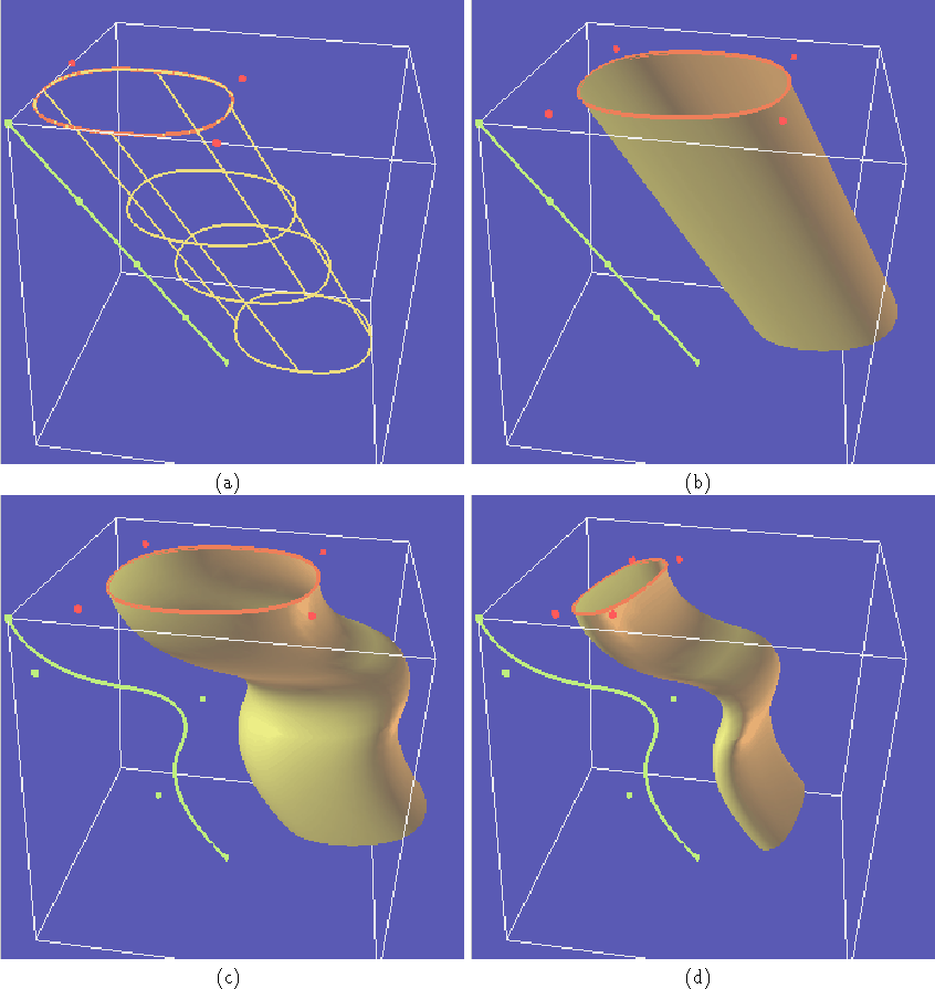
We present three examples in the cross-sectional design of surfaces. First, Fig. 4 shows a generalized cylinder with 30 control points created by sweeping a green closed curve with 6 control points along the red curve with 5 control points (Fig. 4(a)). The generalized cylinder is interactively sculpted into various shapes by applying spring forces on the green and red cubic D-NURBS curves (Fig. 4(b-d)). Second, Fig. 5 shows a torus with 49 control points generated by swinging the green curve over the red curve (Fig. 5(a)). Both generators are closed cubic D-NURBS curves with 7 control points. In Fig. 5(b-d), the torus is deformed interactively by applying a spring force. Third, Fig. 6 shows a 35 control point ``wine glass'' shape obtained by sweeping the green generator curve on the red generator curve in Fig. 6(a). The red closed D-NURBS curve has 7 control points and the green open D-NURBS curve has 5 control points. The glass is interactively sculpted into different swept shapes using spring forces (Fig. 6(b-d)).
Figure 4: Interactive deformation of generalized cylinder. (a) Patch
outline of generalized cylinder created from two D-NURBS generating
curves (control points shown) using sweep operation. (b-d)
Interactive dynamic deformation of either generating curve causes
global deformation of generalized cylinder.
Figure 5: Interactive deformation of torus. (a) Two D-NURBS
generating curves with control points shown and patch outline of torus
generated by swing operation. (b-d) Interactive dynamic deformation
of either generating curve causes global deformation of torus.
Figure 6: Creation and deformation of ``wine glass.'' (a) Two D-NURBS
generating curves with control points and patch outlines of glass
formed by swing operation. (b-d) Deformation of glass caused by
interactive dynamic deformation of D-NURBS generators.