The physical basis of the D-NURBS model and our numerical quadrature approach to computing the mass, damping, and stiffness matrices (Section 6.2) suggests a straightforward technique for trimming D-NURBS curves and surfaces. Surfaces may be trimmed with arbitrary curves defined in the parametric domain, including D-NURBS curves. The trimming of D-NURBS is directly analogous to the trimming of excess material from real-world deformable wires and sheets.
Consider a D-NURBS patch that is intersected by a trimming curve. The values of material properties--mass, damping, elasticity densities--over the portion of the patch that extends outside the trimming curve should not affect the dynamics of the trimmed model and are set to zero. The Gauss quadrature proceeds normally, but abscissas that sample zero physical parameters make no contribution to the summation. Of course, a patch may be disregarded if it falls completely outside the trimming boundary. Note that the integrands are discontinuous at the boundary due to the sudden transition of the the physical parameter values. While this does not destroy the correctness of Gauss quadrature, we can expect reduced accuracy since the integrand is not smooth. There is no easy way around this potential problem for arbitrary boundary curves, other than to use Monte Carlo integration and pay the penalty of slow asymptotic convergence [27]. Fortunately, in practice, the D-NURBS model appears tolerant of the reduced integration accuracy in boundary elements.
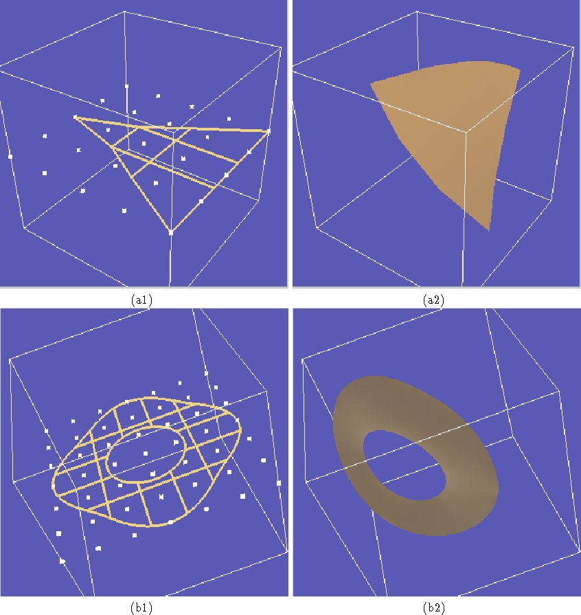
Fig. 1 illustrates the trimming of D-NURBS surfaces using D-NURBS trimming curves in the parametric domain. Fig. 1(a) shows the creation of a triangular surface with three linear curves each with 4 control points. Fig. 1(b) shows a trimmed annular surface defined by two circular trimming curves each with 25 control points. Snapshots are shown of the trimmed surfaces undergoing dynamic deformations in response to applied forces.
Figure 1: Trimming D-NURBS surfaces: (a) triangular D-NURBS surface;
(b) annular D-NURBS surface. (a1) Patch outlines and control points (white)
with linear trimming curves. (a2) Interactive dynamic deformation of
trimmed triangular surface. (b1) Patch outlines and control points
with concentric trimming curves. (b2) Interactive dynamic deformation
of annular surface.