UML
Software engineers often have to communicate properties of the systems
they develop with other stakeholders who may or may not be familiar
with the technical details of the system that is being examined.
UML provides a unified, consistent way to communicate
information about software systems in a way designed to be
intuitive for both technical and non-technical individuals.
Many tools exist that support working with UML that serve to
support the development of a UML model and expressing that model by
generating graphical artifacts as specified by the UML standard.
This laboratory exercise will introduce you to one such tool, ArgoUML.
We'll use ArgoUML to develop four commonly
encountered UML artifacts:
- use case diagram
- state diagram
- class model diagram
- sequence diagram
The diagrams you create will model aspects of a simple case
study wherein you've been contracted to create a new computer system
for a university library. The system you are to develop will
replace the library's antiquated card catalog and their manual,
paper-based method for keeping track of what has been lent out to
library members. For each diagram, we'll introduce the basics
of working with ArgoUML to create that diagram and then you will be
charged with translating a description of the system to be developed
into the desired UML artifact.
Software
This lab requires an installation of ArgoUML.
The following screenshots and
procedures were developed using ArgoUML version 0.32.
Use case diagram
A use case diagram is a simple drawing which documents the behavior of
a system from the user's point-of-view. It identifies the
external entities (known as actors) that will work with your system as
well as what they will be doing with your system (the "use cases" for
those actors). When you start ArgoUML, it will create a
default model called "untitledModel". This is the root node
of your model and will contain all the artifacts that we will be
creating. If you expand this root node, you will see that it
has already been pre-populated with a class diagram and a use case
diagram. We'll return to the class diagram later, but for now
we'll focus on the use case diagram. Clicking on the
pre-populated use case diagram entry in the model will display the
(currently empty) use case diagram in the main edit window.
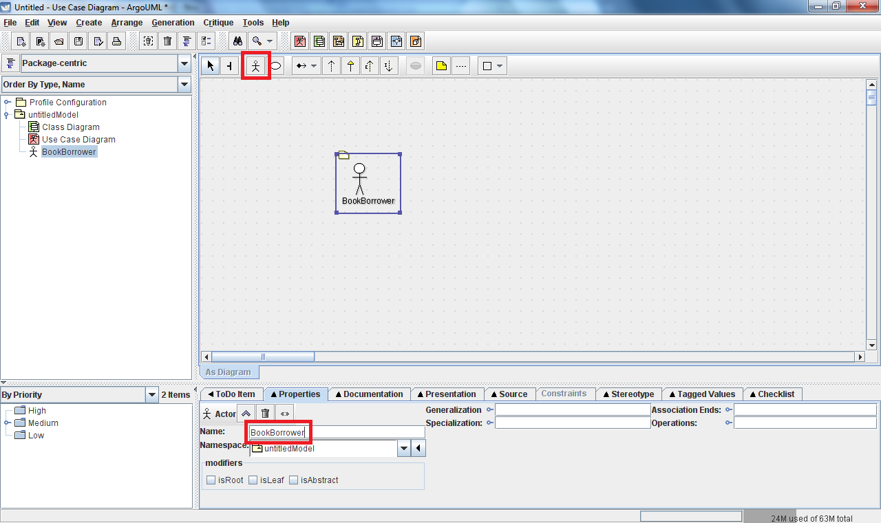
Actors
Actors can be added to the use case diagram by selecting the "New
Actor" tool from the main edit window's toolbar. Once the
tool has been selected, click anywhere in the diagram window to place
an actor in that location. Each actor in your system should
have a short descriptive name. Add this information by
filling in the "Name" field in the "Properties" tab located below the
diagram. All these features are shown below:
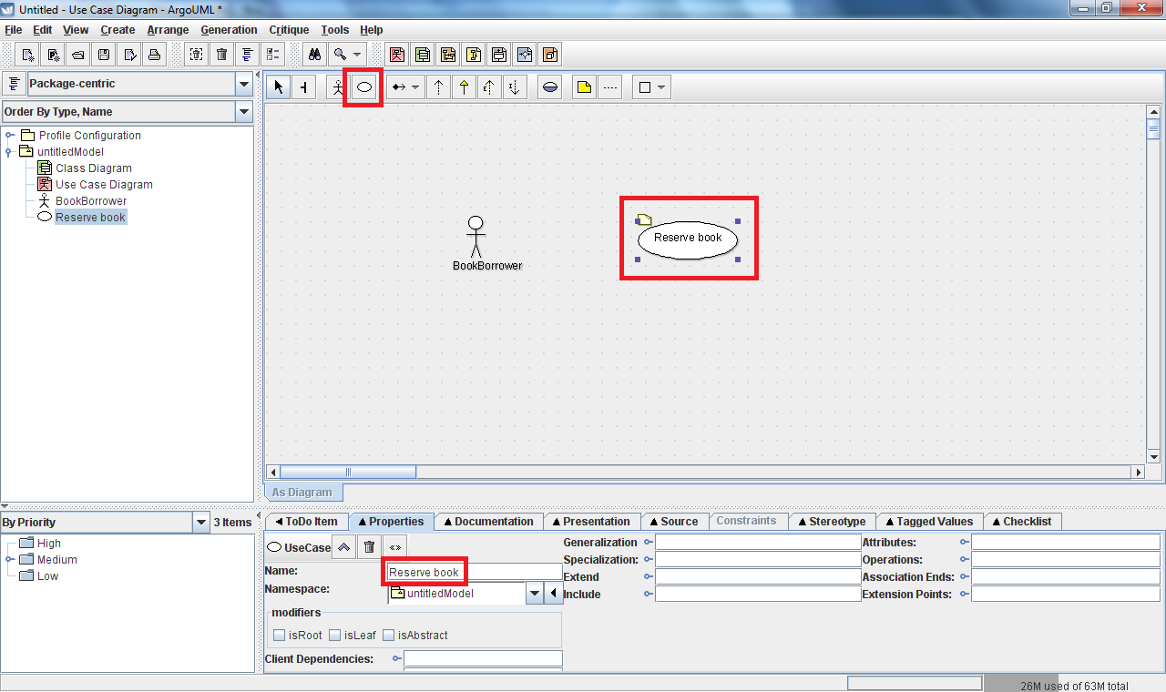
Use cases
Use cases can be added to the use case diagram by selecting the "New
Use Case" tool from the main edit window's toolbar. Once the
tool has
been selected, click anywhere in the diagram window to place a use case
in that location. Each use case in your system should also
have a short
descriptive name. Add this information by filling in the
"Name" field
in the "Properties" tab located below the diagram. Again, all
these features
are shown below:
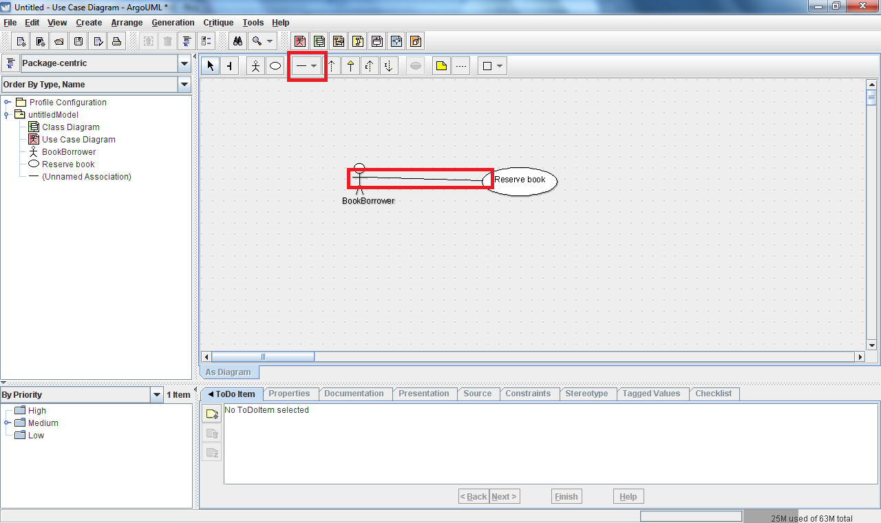
Associations
Use cases and actors are linked by an "association" which indicates
that a particular actor is expected to need to use the system in a
given way. To notate these association between actors and use
cases you'll need to draw a line representing this association.
This can be added to the diagram by selecting the "New
Association" from the edit toolbar. You may need to use the
dropdown button next to the toolbar item group in order to select the
appropriate tool. Once this association tool has been
selected, click and hold on an actor and drag the mouse over to the use
case with which you want them to be associated. You can
associated multiple actors with a given use case, or multiple use cases
with a single actor. You can name your associations if you
like, but this is not required. An example of a simple
associated actor/use case is given below:
Exercise
Translate the following English
statements into a representative use
case diagram:
The
system shall have the following four types of
actors: BookBorrower, JournalBorrower, Browser, and Librarian.
A user playing the role of a BookBorrower shall be able to
reserve a book, borrow a copy of a book, return a copy of a book, and
extend the loan of a book. A JournalBorrower shall be
able to
borrow a journal and return a journal. A Browser shall be
able to browse, and a librarian shall be able to update the catalog.
State diagrams
Perhaps the most familiar of the UML diagram types, state diagrams are
used to communicate how parts of a software system react to specific
stimuli. To create a state diagram in ArgoUML, right-click on
the top-level model node on the left-hand side of the tool and select
the "Create Diagram -> New Statechart Diagram" menu
item. This will add a new state machine, "(Unnamed State
Machine)", as a child node in the model tree. Expand this
node and you'll find the statechart diagram we just created.
The "state machine"-> "state diagram" hierarchy we
see here is
provided by UML in order to allow one state machine to span across
multiple state diagrams. By default the state diagram created
will be named "untitledModel 0" - feel free to rename this to something
more descriptive using the "Properties" tab below the edit window.
Click on the state diagram entry in the model tree and the
empty state diagram will be presented in the edit window.
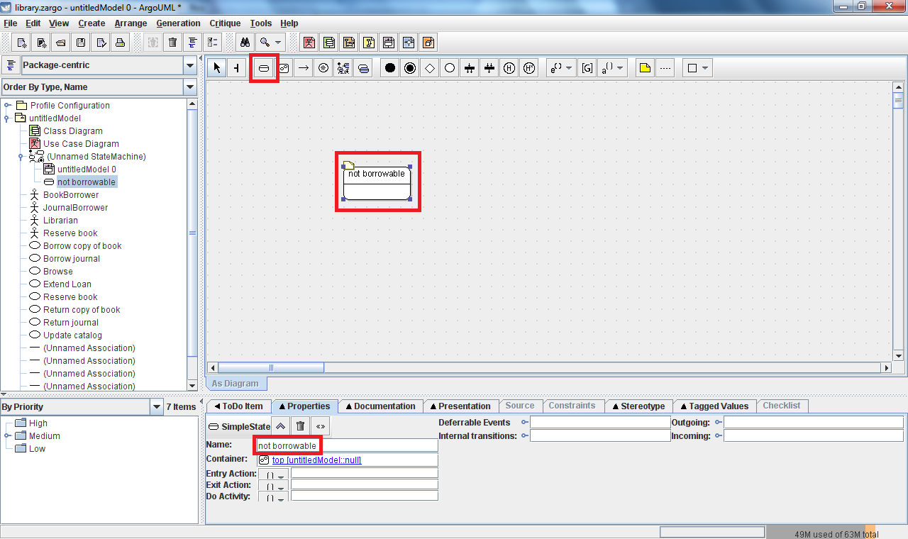
States
States can be added by clicking on the "New Simple State" toolbar
button and then clicking somewhere within the edit window to indicate
where you would like the state to be placed. Each state
should be given a short descriptive name, which can be entered in the
"Name" field within the "Properties" tab. The essential user
interface elements you'll need are called out below.
Transitions
Movement by the system from one state to another is indicated by adding
a "Transition" from one state to another. To add a transition
between states, click on the "New Transition" tool from the edit
toolbar. Then click and hold on the state in which the
transition begins and drag the mouse to the state to which the
transition ends.
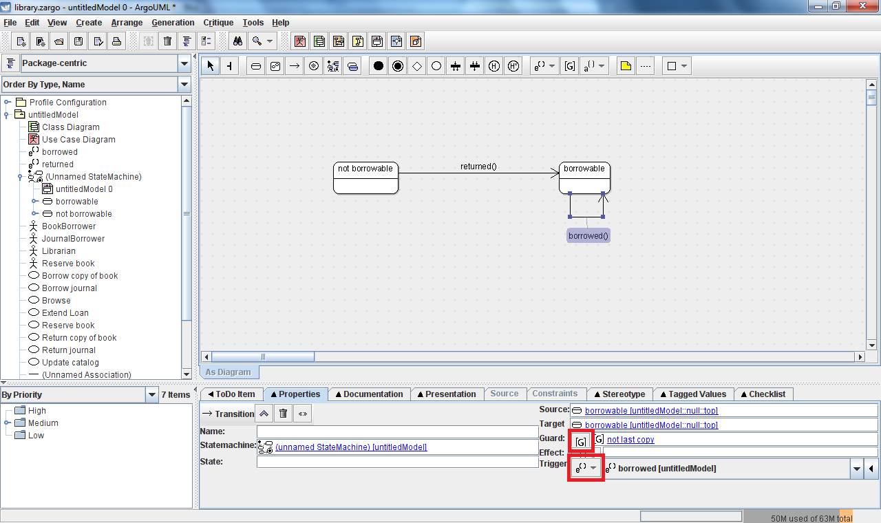
Annotations
Transitions are almost always annotated with additional information
regarding actions that cause the transition to occur (triggers) and
things that will happen when the transition occurs (effects).
Additionally, a transition's triggers can be specified to
only be valid under certain conditions (guards). ArgoUML
supports all of these constructs, and the appropriate annotations can
be added within the "Properties" tab. To add a trigger,
effect, or guard click on the tool button located adjacent to the
respective annotation you wish to add (where different sub-types of
actions are available, we will almost always use the "Call" type as
this corresponds to the familiar action of calling an object's method).
See the figure below for an example showing two transitions:
- "not borrowable"
transitioning to "borrowable": this transition represents a transition
triggered by a call to "returned"
- "borrowable" transitioning
to "borrowable": this self-transition represents a transition triggered
by a call to "borrowed", but it is guarded (i.e.: won't happen unless)
it is not the last copy
Note: Creating a transition
from a state to itself (a so-called "self transition") is not intuitive
in ArgoUML. To enter such a transition use a "u-turn" when
drawing the transition - namely click on the state and drag out a
distance from the state, release the mouse, move the mouse slightly,
click again, and then finally click back on the state. This
will create the desired self transition.
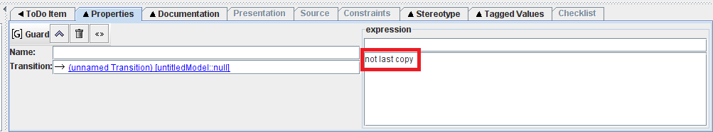
Note: To define a guard, the desired expression should be entered in
the large text box at the bottom right (as seen above), not the name
field or the small textbox directly under "expression". The
small text box can be used to specify a language for the expression
(and there are tooltips to indicate this), but it is not immediately
apparent from the user interface.
Exercise
During the process of designing the
new library system it
was discovered that one class of the library system objects
would be a "Book". Perhaps not as obvious is that an
additional (but closely related) object class would be one
for specific copies of a book. For this exercise you
will be designing a simple subset of the state
machine that is
implemented as part of the "Book" class. Translate the
following English statements into a representative state diagram which
models the behavior of the "Book" class of objects:
A
Book should either be borrowable or not borrowable. If a Book
is currently borrowable, it should accept notifications that it was
returned unconditionally. Additionally, if the book is
borrowable and it is notified that a copy of it has
been borrowed, then it should transition to not being
borrowable only if it was the last copy that was just borrowed -
otherwise it should remain borrowable. Conversely, if the
book is not currently borrowable, then it should transition
back to being borrowable whenever it is notified that a copy of the
book is returned.
Class diagrams
Class diagrams provide a way to document the structure of a system by
defining what classes there are within it and how they are related.
ArgoUML automatically includes a class diagram in all of the
models it creates. The default class diagram name is "Class
Diagram", click on it to open the blank class diagram canvas in the
edit window.
Classes
As you would expect, the basic building block of a class diagram is the
class. To add a new class to your class diagram, click on the
"New Class" tool in the class diagram's edit toolbar and click anywhere
in the edit window where you would like the class to be placed.
At a minimum, each class should have a name, which can be
supplied using the "Name" field in the "Properties" tab for a given
class.
Operations
Classes can contain additional information about the operations they
support. Operations define the ways in which objects interact
with each other (these operations are often analogous to methods in
many programming languages). Operations can be added to a
class by selecting the desired class in the edit window and clicking
the "New Operation" tool from the edit window's toolbar. This
will add a new operation to the class that can be modified using the
"Properties" tab as seen below.
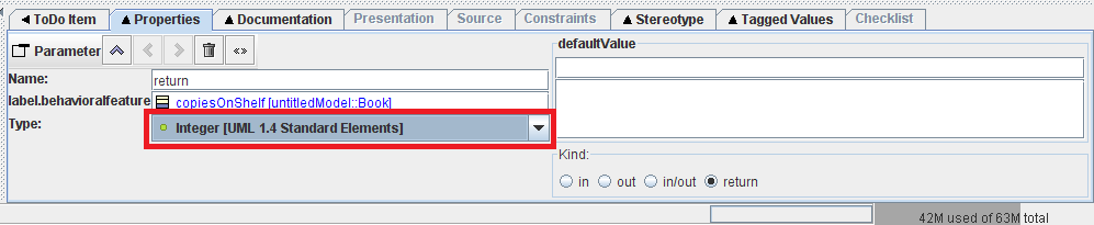
The most common properties that you'll want to modify will be to give
the operation a name and to specify information about the parameters it
uses. Parameters are often used to record the arguments the
operation/method is expected to take and the type (if any) it uses to
return information. Expanding the parameter list box by clicking on
"Parameter" in the "Properties" tab will give you access to additional
parameter related tools such as "New Parameter" that allow you to add
parameters for the operation. By default, all operations have
a "return" parameter with type <none> that serves as a
placeholder for the return type. Double-clicking on a
parameter in the parameter list will will open an additional edit
screen for the selected parameter in the "Properties" tab.
This edit screen allows you to modify parameter properties
such as its name and type. A sample parameter edit screen
showing the "return" parameter modified to return an Integer
is shown below.
Note: UML provides standard primitive types for you. You can
also specify the type to be a class that you've added to your model
(such as the Book class) as well.
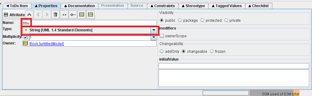
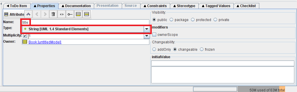
Attributes
In addition to operations, classes will also often have attributes
which are used to describe the data contained in an object of the class
(these attributes are often analogous to fields in many programming
languages). Attributes can be added to a class by selecting
the desired class in the edit window and clicking the "New Attribute"
tool from the edit window's toolbar. This will add a new
operation to the class and will open a new edit screen in the
"Properties" tab. In this edit screen you can modify the
attribute properties such as its name and type. A sample
attribute edit screen is shown below.
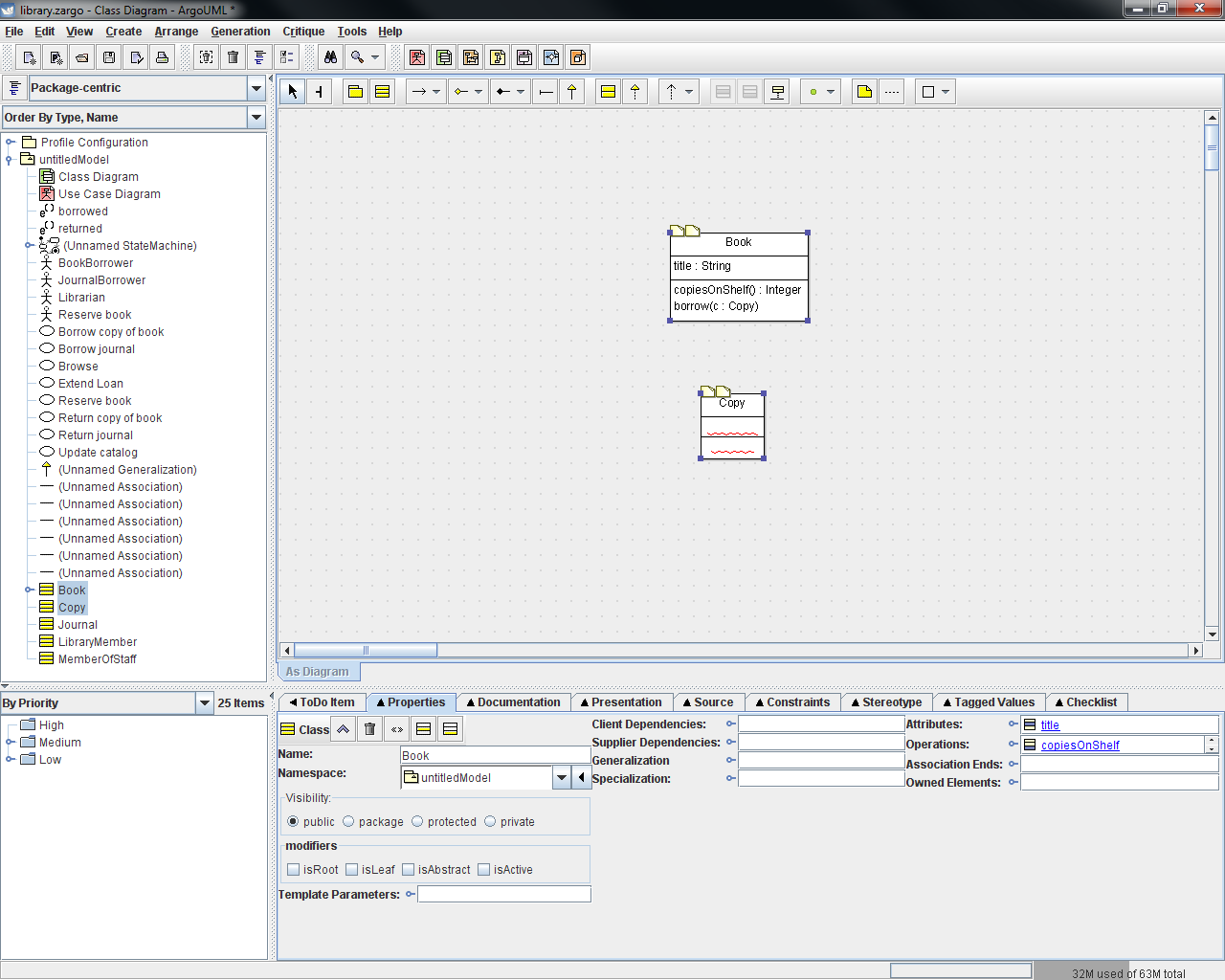
A sample class diagram using a class with attributes and properties is
shown below.
Associations and
Generalizations
The relationships between classes are often described
using associations and generalizations. While
classes often correspond the "nouns" in a system, associations
correspond to the "verbs". They describe relationships such
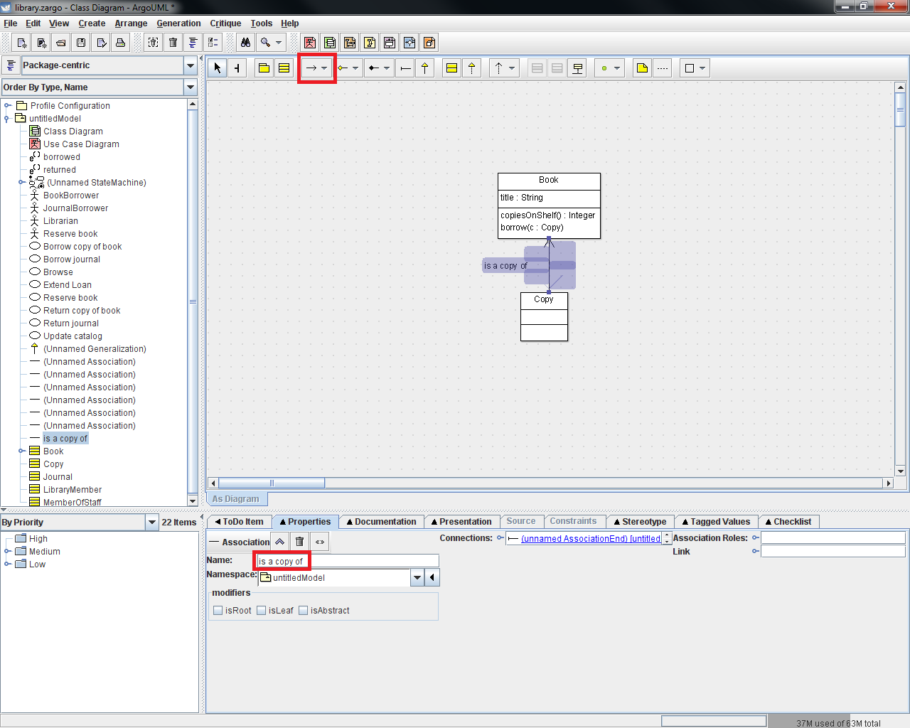
as "is a copy of" and "borrows/returns". Associations can be
added between classes in ArgoUML by selecting the "New UniAssociation"
tool in the edit toolbar and then clicking and holding on one class in
the diagram and dragging the mouse to the class to which you want to
create the association. You'll generally want to give names
to your associations, and this can be done using the "Properties" tab
edit screen for the association. A sample class association
is shown below.
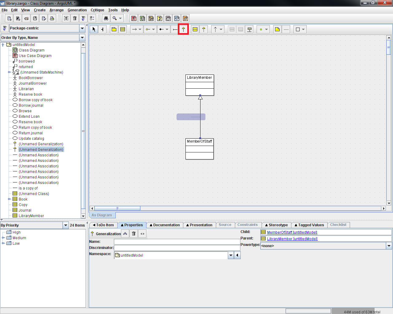
Another important relationship between classes is a "generalization".
Generalizations describe relationships that are often
analogous to inheritance in programming languages.
Generalizations can be added by clicking on the "New
Generalization" tool in the edit toolbar and then clicking and holding
on the more specific class and then dragging the mouse to the class
which is a generalization of it. A sample showing a
generalization relationship between two classes is shown below.
Exercise
Translate the
following English statements into a representative class diagram which
models the structure the library system:
The
library system should allow for the representation of the following
roles: LibraryMember, MemberOfStaff, Journal, Book, Copy.
LibraryMembers can interact with Copy objects in that they
can borrow/return them. Likewise, MemberOfStaff objects can
borrow/return Journals. It's also important that we have a
relationship between Book and Copy where Copy is a copy of a Book.
Also, note that MemberOfStaff
objects will always be
LibraryMembers as well and should be able to do everything a
LibraryMember can do.
Lastly, let's add some additional details to the Book class: every Book
will keep track of its title, which is a string. It should
respond to a copiesOnShelf message with an integer, and it should
accept a borrow message that has an input parameter of type Copy.
Sequence Diagrams
The last UML diagram type we'll be working with is a sequence diagram.
A sequence diagram is sub-type of a more broad category of
UML diagrams called interaction diagrams. A sequence diagram
shows how actors and/or objects interact with each other by providing a
timeline of messages being passed from one to the other. Each
object/actor has a representation of its own timeline (known as a
lifeline) in which time is assumed to pass as we move from top to
bottom of the diagram. To create a sequence diagram in
ArgoUML, right-click on the root node of your model and select "Create
Diagram -> "New Sequence Diagram". This will add a new
sequence diagram (nested in a collaboration node) to the model and open
a blank sequence diagram canvas in the edit window.
Actors/Objects
The first step in defining the sequence diagram is to add the
actors/objects that are involved in the interaction to be displayed.
You can add generic objects, but in general it is best to
associate the lifeline with a type that we've already defined in the
model. For this, search the model tree on the left of the
screen to find a class (which was defined in your class
diagram) or an actor (which was defined in your use case diagram) that
represents the type of the object/actor you wish to add to the diagram.
Click and hold on this entry and drag it onto the sequence
diagram canvas. This will create a lifeline (referred to as a
"Classifier Role" in ArgoUML) that is associated with the selected type
in your diagram. As usual, properties of this model member
can be modified using the "Properties" tab - in general at least a name
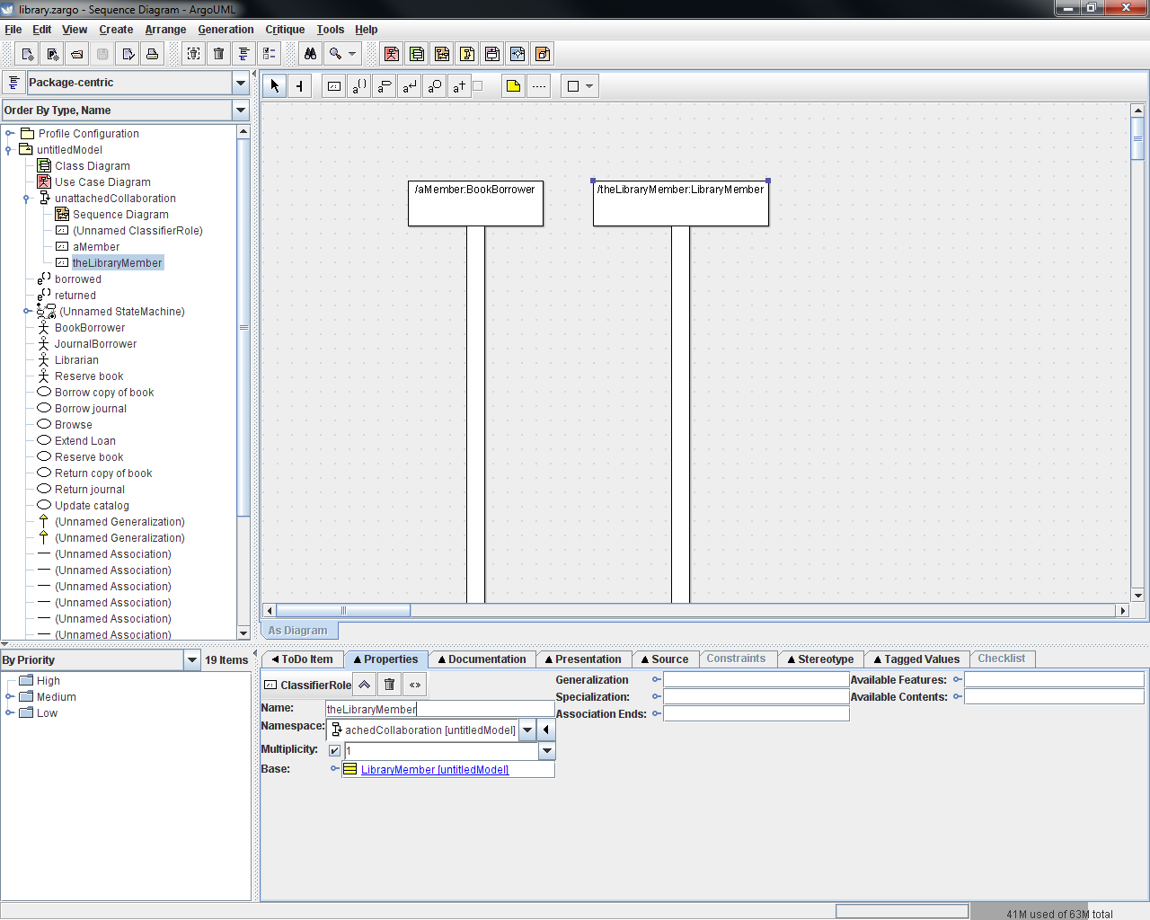
should be provided. The screenshot below shows a sequence
diagram that has been populated with two lifelines: on the left is an
instance ("aMember") of an actor ("BookBorrow"), on the right there is
an instance ("theLibraryMember") of a class ("LibraryMember").
Messages
With the actor and object instances placed in the diagram, the next
step is to depict the sequence of messages that are passed between each
instance. Most often these message will represent the calling of a
method, so to add these messages you'll select the "New Call Action"
tool from the edit toolbar and then click-and-hold on the instance
which will be generating the message and drag it to the instance which
will be receiving it. This will create a message call and
return action in the sequence diagram. As usual, you will
need to edit the properties for this message using the "Properties" tab
where you can use the "Name" field to record information about the
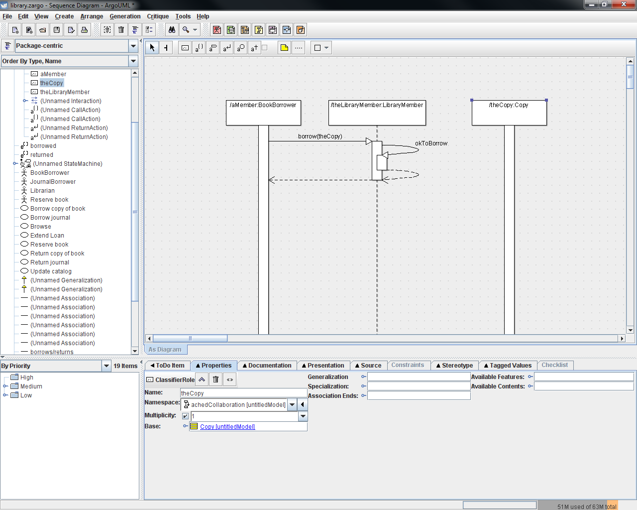
message. The snapshot below shows the sequence diagram from
above updated with two messages: one from "aMember" to
"theLibraryMember" requesting to borrow a specific copy, and another
showing that "theLibararyMember" will send a message to itself to see
if it's alright for the member to borrow the copy. The second
diagram has also been updated to include a third lifeline for
"theCopy", an instance of the "Copy" class, since "theCopy"
is involved in the interaction between "BookBorrower" and
"theLibraryMember".
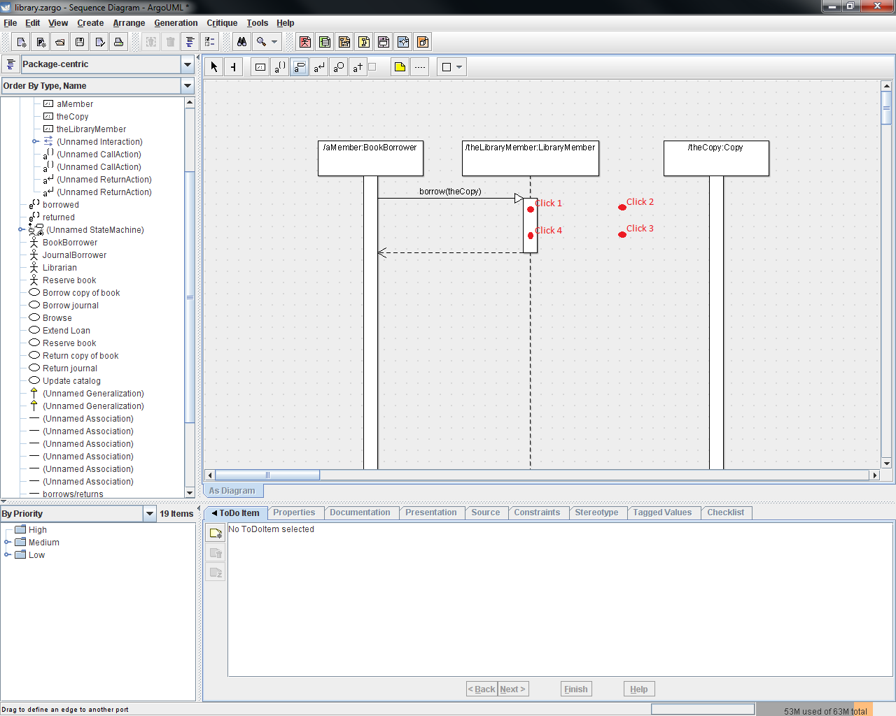
Note: As we've seen before, getting ArgoUML to allow a message to be
passed to the same object that is generating it is not initially
intuitive. To create this message-to-self you'll need to use
the "U-turn" method discussed earlier for state diagrams.
Click-and-hold on the instance you wish the message to be
generated by and drag away, release the mouse, click in yet another
location away from the instance, and finally click back on the
instance. Note that your second and third clicks must be far
sufficiently far away from the lifeline for this to work -
specifically, they must be further away than the bounding box for the
box at the top of the lifeline. See below for an example of
the sequence of clicks that will successfully generate a
message-to-self.
Exercise
Translate the
following English statements into a representative sequence diagram
which
models the interaction necessary for a member to borrow a book:
Four
actors/objects will be involved in a
book borrowing interaction: a
BookBorrower named aMember, a LibraryMember named theLibraryMember, a
Copy named theCopy and a Book named theBook. aMember will
request to borrow theCopy by sending a message to theLibraryMember.
theLibraryMember will then check with itself to make sure
it's ok for the borrowing to occur and then notify theCopy that it is
going to be borrowed. theCopy will then in turn notify
theBook that it has been borrowed. Once all of these nested
operations are complete, aMember is now borrowing the book!
Reference materials:
- Perdita Stevens with Rob Pooley, Using
UML: Software
Engineering with Objects and Components, Updated Edition,
ISBN 0-201-64860-1
Developed with guidance from
Miryung Kim
Copyright
(c) 2011
Professor Miryung Kim and a course development TA Evan Grim
Permission is granted to copy, distribute and/or modify this document
under the terms of the GNU Free Documentation License, Version 1.1 or
any later version published by the Free Software Foundation; with no
Invariant Sections, no Front-Cover Texts, and no Back-Cover Texts.
A copy of the license can be found on the GNU web site here.